
MSG — I2C, SPI and UART
Description
Section titled “Description”With the protocol set to i2c, spi or uart, MSG performs one raw bus transaction with a chip on the Network tree: a register read or write over I2C or SPI, or a burst of bytes over a serial port. The transfer is done inside the scan on the rung’s rising edge, and each byte lands in, or comes from, one element of the Local array. Use these for a chip that has no catalog entry, for a register the catalog entry does not expose, or for a simple serial device that takes a fixed frame. Do not use them for chips the catalog already services (an ADS1115, a BME280, a DS3231’s time) unless you need the raw register, and do not expect any framing or checksum on UART; you get bytes, nothing more.
Operands
Section titled “Operands”| Operand | Type | Format | Valid Range | Required | Description |
|---|---|---|---|---|---|
| Direction | Choice | read / write |
— | Yes | Read fills Local; write sends Local. |
| Protocol | Choice | i2c, spi, uart |
Must match the port the device is on | Yes | I2C devices sit on the I2C port, SPI devices on SPI, UART devices on Serial1… or SoftwareSerial. |
| Device | Network device | Name | A module on that port | Yes | Supplies the I2C address, the SPI chip-select pin or the UART baud and pins. |
| Local data | Tag | INT, DINT, REAL or BOOL array, or Buf[n] |
Window must fit | Yes | One byte per element. An INT array is the natural choice; each element receives 0 to 255 on a read, and its low byte is sent on a write. |
| Length | INT | 1 to 128 | Fits the array | Yes | Bytes transferred. |
| Remote register | INT | 0 to 65535 | 0 to 255 is what a byte-addressed chip understands | I2C, SPI | The register address sent before the data. Ignored for UART. |
Scan Behavior
Section titled “Scan Behavior”Prescan
Section titled “Prescan”Nothing.
Rung-condition-in is false
Section titled “Rung-condition-in is false”Nothing. The edge memory is armed.
Rung-condition-in is true
Section titled “Rung-condition-in is true”On the rising edge the transaction runs to completion inside the scan:
| Protocol | Read | Write |
|---|---|---|
| I2C | Start, address, register byte, repeated start, request Length bytes, one byte per Local element. Bytes the chip does not supply leave those elements unchanged. | Start, address, register byte, Length bytes from Local, stop. |
| SPI | Chip-select low, send register OR 0x80 (the common read flag), clock Length bytes in, chip-select high. |
Chip-select low, send register, clock Length bytes out, chip-select high. |
| UART | Copy whatever bytes have already arrived in the port’s receive buffer into Local, up to Length. It does not wait for bytes. | Send Length bytes from Local. |
The status tag is accepted but not filled by these protocols.
Postscan
Section titled “Postscan”Nothing.
Example
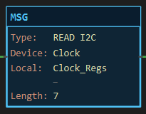
Section titled “Example”The example on the MSG page is an I2C read: seven registers from a DS3231 clock at address 0x68 into Clock_Regs, register 0, length 7. The same three figures apply here.
For a write, the mirror image sends Clock_Regs[0..6] back into the chip’s registers 0 to 6: set Direction to write, keep everything else. On the DS3231 that sets the time.
Values before and after: a read leaves each element with one byte of the chip’s register file; a write leaves the chip’s registers holding the low byte of each element. In the simulator nothing changes.
See Also
Section titled “See Also”- MSG — the instruction, its dialog and status tag
- MSG — Modbus RTU — a serial protocol with framing and checksums, for slaves that speak it
- Adding Network Devices — putting the chip on the tree
- Communication Instructions — Category index
Bytes, not words. These transfers move bytes. A 16-bit register read over I2C arrives as two elements, high byte first on most chips; combine them with a CPT such as Hi * 256 + Lo or an MOV into the bits you need. Modbus and EtherNet/IP, by contrast, marshal whole INT, DINT and REAL values for you.
The bus is started for you. Wire.begin(), SPI.begin() and the serial port’s begin(baud) are emitted once in setup() for every port that has a device on it. The I2C address, SPI chip-select and UART baud come from the device, not the instruction.
SPI read flag. The read sends register OR 0x80 because that is the convention of most register-file chips (MPU-6050, BME280, MAX31865). A chip that uses a different read marker needs a catalog entry or a LIB instead.
UART does not wait. A UART read on the rising edge copies only the bytes that have already arrived. Trigger it a little after the device has answered, for example one scan after the write’s rung, or from a short timer.
SoftwareSerial. On a board with one hardware UART (Uno, Nano) a UART device goes on the SoftwareSerial port with the RX and TX pins set on the device; the project may have only one SoftwareSerial link. Keep it at 9600 or 19200 baud.
No D0/D1. The primary Serial is the Get Online link and is never a MSG port.
Applies to LadderIDE >=1.2.2 · Last reviewed 2026-09-11 · Screenshots verified 2026-09-11