
MSG — DF1
![MSG instruction block for a DF1 write: Type: WRITE DF1, Device: Micro, Local: DataToMicro with its value [99, 6], Length: 2](/assets/docs/instructions/communication/comm-df1-block.png)
Description
Section titled “Description”With the protocol set to df1, MSG reads or writes an Integer or Float data file in an Allen-Bradley controller over its DF1 serial port: a MicroLogix, an SLC 500, or a CompactLogix Channel 0 with a PLC/SLC message mapping. The Arduino is the DF1 master and speaks PCCC full-duplex with CRC, the same wire protocol RSLinx uses on a serial driver. The rung’s rising edge queues the request; a shared service runs the link on every scan. Use it where the PLC has a serial port and no Ethernet, or where a spare Channel 0 is the easiest way in. Do not run it on the primary Serial; that suppresses the Get Online monitor.
Operands
Section titled “Operands”| Operand | Type | Format | Valid Range | Required | Description |
|---|---|---|---|---|---|
| Direction | Choice | read / write |
— | Yes | Typed Read (0xA2) or Typed Write (0xAA) of the remote file. |
| Protocol | Choice | df1 |
Selected for you when the device is a DF1 PLC | Yes | |
| Port | Comm port | Serial1, Serial2, Serial3 or SoftwareSerial |
Not Serial |
Yes | The transport follows the tree: a hardware UART is full-duplex and leaves USB free; SoftwareSerial uses the RX/TX pins set on the device. |
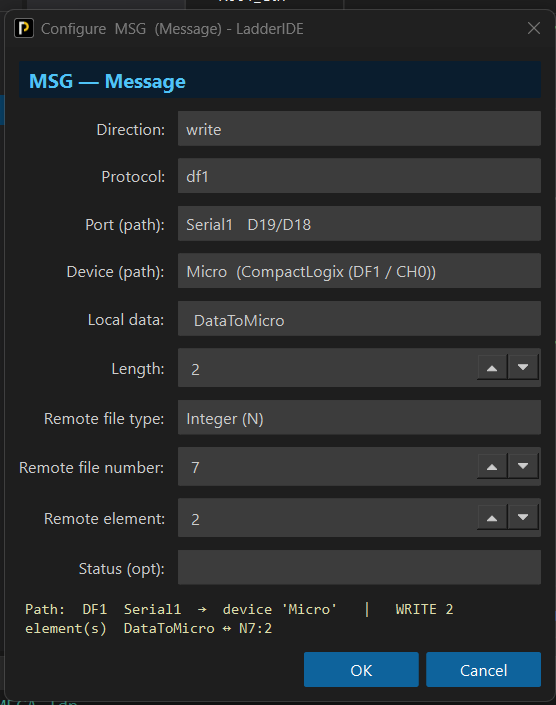
| Device | Network device | Name | A CompactLogix (DF1 / CH0) or SLC 500 / MicroLogix (DF1) device on that port | Yes | Carries baud, node numbers (DST = PLC, SRC = Arduino), the SoftwareSerial pins and the debug switch. All DF1 MSGs share this one link. |
| Local data | Tag | INT array for an Integer file, REAL array for a Float file; or Buf[n] |
Window must fit | Yes | The file type is tied to this tag’s type. |
| Length | INT | 1 to 128 | Fits the array | Yes | Elements (words for N, floats for F). |
| Remote file type | Choice | Integer (N) or Float (F) | Must match the Local type | Yes | Follows the Local tag automatically; a mismatch is a build error. |
| Remote file number | INT | 0 to 255 | The PLC’s file, e.g. 7 for N7 | Yes | |
| Remote element | INT | 0 to 999 | Start element, e.g. 0 for N7:0 | Yes | |
| Status (opt) | CONTROL tag | Name | No | Accepted but not filled by DF1 in this release; the members stay 0. |
Scan Behavior
Section titled “Scan Behavior”Prescan
Section titled “Prescan”Nothing. The serial port opens in setup() at the device’s baud.
Rung-condition-in is false
Section titled “Rung-condition-in is false”Nothing new. A queued request continues. The edge memory is armed.
Rung-condition-in is true
Section titled “Rung-condition-in is true”On the rising edge the request is queued. The DF1 service, round-robining every DF1 MSG on the link, sends the PCCC command (Typed Read or Typed Write of N<file>:<element> or F<file>:<element>, Length elements), handles the DF1 ACK/NAK/ENQ handshake and CRC, and on a read copies the reply into Local. A NAK or a missing reply is retried up to three times, then the request is dropped. There is no status tag feedback in this release, so watch the data itself, or the device’s debug output on USB, to confirm traffic.
Postscan
Section titled “Postscan”Nothing.
Example
Section titled “Example”Scenario: A Mega talks to a MicroLogix over Serial1. Every fast pulse reads two words from N7:0-1; every medium pulse writes two words to N7:2-3. This is the MEGA.ldp example project, routine R001_Ctrl.
Network tree: Micro — CompactLogix (DF1 / CH0) device on Serial1, 19200 baud, DST node 0, SRC node 1.
Tags:
Pulse.Fast,Pulse.Med— pulse bits from a flip-flop blockMicroData— INT[2], read from the PLCDataToMicro— INT[2], preset[99, 6], written to the PLC
Rung 0 (read):
—|XIC Pulse.Fast|———[MSG READ DF1 Device Micro Local MicroData Length 2 N7:0]———Rung 1 (write):
—|XIC Pulse.Med|———[MSG WRITE DF1 Device Micro Local DataToMicro Length 2 N7:2]———The figures follow the write rung; the read rung is the same block with Direction read, Local MicroData and element 0.
Write rung, pulse off. Nothing queued. The face lists DataToMicro as [99, 6].
![Figure 2 — DF1 MSG write rung false: Pulse.Med off, wire dark, the block showing WRITE DF1, Micro, DataToMicro [99, 6], Length 2](/assets/docs/instructions/communication/comm-df1-example-rung-1.png)
Write rung, pulse on. The write is queued; on hardware N7:2 and N7:3 become 99 and 6.
![Figure 3 — DF1 MSG write rung true: Pulse.Med on, the wire lit through the block showing WRITE DF1, Micro, DataToMicro [99, 6], Length 2](/assets/docs/instructions/communication/comm-df1-example-rung-2.png)
Values before and after: N7:2-3 → 99, 6; on the read rung MicroData 0,0 → N7:0-1. In the simulator nothing is sent; the pulses still blink, so a frame catches the rung in either state.
See Also
Section titled “See Also”- MSG — the instruction and its dialog
- MSG — EtherNet/IP — the Ethernet route into a Logix controller
- MSG — Modbus RTU — the other serial master
- Adding Network Devices — the PLC device, its port and node numbers
- Communication Instructions — Category index
A level converter is mandatory. The PLC’s RS-232 swings ±12 V; an Arduino pin does not survive it. Put a MAX3232-class board between them. Wiring, PLC-side setup and the CompactLogix message mapping are in the DF1 setup guide shipped with the IDE.
File type follows the Local tag. INT and DINT locals read Integer (N) files, two bytes per element; REAL locals read Float (F) files, four bytes per element. The dialog syncs the dropdown when you pick the Local tag; leave it that way unless you mean to read a float file into integers.
CompactLogix needs a mapping. A Logix controller has no N7 until you map a tag to file 7 in the controller’s PLC/SLC Message settings. The MicroLogix and SLC already have their files.
One link per project. All DF1 MSGs share the device’s port. On an Uno that is the SoftwareSerial port, which a Modbus RTU device cannot also use; a Mega with its spare UARTs is the recommended board.
Debug. The device’s Debug switch prints each transaction’s verdict on the USB serial and suppresses the monitor while it is on.
Verified in both directions against a MicroLogix 1100 on a Mega’s Serial1.
Applies to LadderIDE >=1.2.2 · Last reviewed 2026-09-11 · Screenshots verified 2026-09-11