
MSG — Modbus RTU
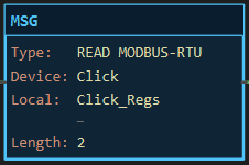
Description
Section titled “Description”With the protocol set to modbus-rtu, MSG reads or writes registers or bits in a Modbus RTU slave over a serial line: an RS-485 multidrop or an RS-232 point-to-point link to a small PLC, a drive, a power meter or a remote-I/O block. The Arduino is the master; the rung’s rising edge queues a request and a master service runs the bus a little on every scan, one bus per serial port, so the logic never waits. Areas, marshalling and the status tag are the same as Modbus TCP; only the transport differs. Use it wherever a slave has a serial port and a register map. Do not put two masters on one bus, and do not expect it to work through the primary Serial; that port is the Get Online link.
Operands
Section titled “Operands”| Operand | Type | Format | Valid Range | Required | Description |
|---|---|---|---|---|---|
| Direction | Choice | read / write |
Write is refused on Input Register and Discrete Input areas | Yes | |
| Protocol | Choice | modbus-rtu |
Selected for you when the device is a Modbus RTU Device | Yes | |
| Port | Comm port | Serial1, Serial2, Serial3 or SoftwareSerial |
A UART port; not Serial |
Yes | Every RTU device on one port shares one master and one bus. |
| Device | Network device | Name | A Modbus RTU Device on that port | Yes | Carries the slave’s unit id (1 to 247), baud, parity, the SoftwareSerial RX/TX pins, an optional DE pin and the 32-bit word order. |
| Local data | Tag | INT, SINT, DINT or REAL array for registers; BOOL array for coils / discrete inputs; or Buf[n] |
Window must fit | Yes | INT/SINT = 1 register, DINT/REAL = 2, BOOL = 1 bit. |
| Length | INT | 1 up to one frame (125 registers, 1968 bits) | Build error above the limit | Yes | Elements of Local. |
| Start address | INT | 0 to 65535 | Yes | 0-based protocol address. | |
| Modbus area | Choice | Holding Register, Input Register, Coil, Discrete Input | Yes | ||
| Status (opt) | CONTROL tag | Name | One per MSG | No | EN, DN, ER, POS = exception code; 255 = timeout, CRC error, wrong unit or function in the reply. |
Scan Behavior
Section titled “Scan Behavior”Prescan
Section titled “Prescan”Nothing. The serial port is opened in setup() at the device’s baud; 8N1 on SoftwareSerial, the device’s parity on a hardware UART.
Rung-condition-in is false
Section titled “Rung-condition-in is false”Nothing new. A queued or in-flight request continues. The edge memory is armed.
Rung-condition-in is true
Section titled “Rung-condition-in is true”On the rising edge the request is queued; with a status tag, EN = 1, DN = ER = 0. The master service takes requests one at a time per bus: it raises the DE pin if one is configured, sends unit + function + data + CRC-16, releases the line, and collects the reply until the expected length has arrived or the line has been quiet for the 3.5-character gap. CRC, unit id and function code are checked. Success unpacks a read into Local and sets DN; an exception sets ER with the code in POS; no reply within one second sets ER with POS = 255. Function codes are those of the Modbus TCP page: FC03/16 holding, FC04 input, FC01/05/15 coils, FC02 discrete inputs.
Postscan
Section titled “Postscan”Nothing.
Status Tag Members
Section titled “Status Tag Members”| Member | Data type | Set by | Cleared by | Description |
|---|---|---|---|---|
EN |
BOOL | Rung edge | Service on completion | Queued or in flight. |
DN |
BOOL | Service on success | Next rung edge | Last transfer succeeded. |
ER |
BOOL | Service on failure | Next rung edge | Last transfer failed. |
POS |
DINT | Service | — | Exception code (1 to 4 as in Modbus TCP); 255 = timeout, CRC, unit or function mismatch. |
Example
Section titled “Example”Scenario: An AutomationDirect CLICK PLC on an RS-485 line. Its first two data registers DS1 and DS2 sit at holding-register address 0 and 1. A pushbutton reads them.
Network tree: Click — Modbus RTU Device on the SoftwareSerial port, unit id 1, 9600 baud, no parity, RX D2, TX D3, no DE pin (the transceiver switches direction itself), word order CDAB.
Tags:
Read_Click— Read CLICK registers, BOOLClick_Regs— CLICK DS registers, INT[4]Click_Sts— CLICK message status, CONTROL
Rung 1:
—|XIC Read_Click|———[MSG READ MODBUS-RTU Device Click Local Click_Regs Length 2 Holding 0 Status Click_Sts]———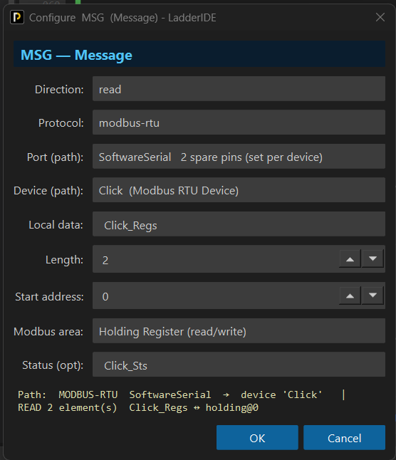
Scan 1 — Read_Click = 0. Nothing queued.

Scan 2 — Read_Click = 1 (rising edge). The request is queued, Click_Sts.EN = 1. On hardware 01 03 00 00 00 02 C4 0B goes out, the CLICK answers with two registers, Click_Regs[0] and [1] take DS1 and DS2, and Click_Sts.DN = 1.

Values before and after: Click_Regs[0..1] 0,0 → DS1, DS2; Click_Sts.DN 0 → 1. In the simulator nothing is sent.
See Also
Section titled “See Also”- MSG — the instruction and its dialog
- MSG — Modbus TCP — the same areas, function codes and binary layout over Ethernet
- MSG — I2C, SPI and UART — raw serial without framing
- Adding Network Devices — the RTU device, its pins and word order
- Communication Instructions — Category index
One master per bus, many slaves. Put every slave on the same RS-485 line under the same port; they differ only by unit id. The build refuses two devices on one port that disagree on baud, parity or pins, a duplicate unit id, or a unit id outside 1 to 247.
SoftwareSerial is 8N1. Parity is only available on a hardware UART. On an Uno set the slave to no parity, 9600 or 19200 baud, and give the device two spare pins; the project may have only one SoftwareSerial link, so a DF1 device cannot share the board.
DE pin. A bare MAX485 needs its driver-enable pin driven; name it on the device. Shields with automatic direction control leave it blank.
Addresses and word order follow the Modbus TCP page: 0-based, vendor offsets removed, DINT/REAL word order set on the device. The CLICK, for instance, documents its DS registers at 400001 and up, which is address 0, and swaps words (CDAB).
Verified against a CLICK C2-03CPU over RS-485 with an Uno and the RS-232/RS-485 shield in its SoftwareSerial mode on D2/D3.
Applies to LadderIDE >=1.2.2 · Last reviewed 2026-09-11 · Screenshots verified 2026-09-11