
OTE — Output Energize
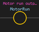
Description
Section titled “Description”OTE (Output Energize) sets a bit to 1 (true) when the rung conditions are true, and clears it to 0 (false) when the rung conditions are false. Use OTE as the output instruction on every rung—it is the most fundamental way to control a digital output, a memory flag, or any writable bit. OTE is not latching; the output follows the rung conditions in real time every scan. Do not use OTE to pulse an output momentarily; use ONS (one-shot) before OTE, or use a timer/counter for timed pulses.
Operands
Section titled “Operands”| Operand | Type | Format | Valid Range | Required | Description |
|---|---|---|---|---|---|
| Address | BOOL or bit member | Tag name or Tag.bit |
Any writable BOOL tag or INT/DINT bit member | Yes | The tag or bit to set. OTE sets this to 1 when the rung is true, and clears it to 0 when the rung is false. If the address is a pin, the firmware writes the logic level to the hardware pin. |
Scan Behavior
Section titled “Scan Behavior”Prescan
Section titled “Prescan”OTE has no persistent state. On the transition to run mode, OTE initializes the bit to its force value (or 0 if not forced).
Rung-condition-in is false
Section titled “Rung-condition-in is false”If the rung conditions to the left of OTE evaluate to false (no power flow), OTE clears the bit to 0. The output is de-energized.
Rung-condition-in is true
Section titled “Rung-condition-in is true”If the rung conditions to the left of OTE evaluate to true (power flows), OTE sets the bit to 1. The output is energized.
Postscan
Section titled “Postscan”OTE has no special postscan behavior. The final logic state is written to the output on the last scan.
Example
Section titled “Example”Scenario: A start button (XIC StartBtn) gates a motor output. When the button is pressed, the motor runs; when released, it stops immediately.
Initial state:
StartBtn= 0 (button not pressed)MotorRun= 0 (motor off)
Rung logic:
—|XIC StartBtn|———(OTE MotorRun)———Scan 1 — Button not pressed:
- Rung-in:
StartBtnis 0 - OTE result: Bit is cleared to 0 (output de-energized)
- Output:
MotorRun= 0 (motor stays off)

Values: StartBtn = 0, MotorRun = 0 (grayed out, de-energized)
Scan 2 — User presses the button:
- Rung-in:
StartBtnbecomes 1 (XIC conducts) - OTE result: Bit is set to 1 (output energized, highlighted in orange)
- Output:
MotorRun= 1 (motor turns on)

Values: StartBtn = 1, MotorRun = 1 (orange highlight, energized)
Scan 3 — User releases the button:
- Rung-in:
StartBtnreturns to 0 (XIC does not conduct) - OTE result: Bit is cleared to 0 (output de-energized)
- Output:
MotorRun= 0 (motor stops immediately)
OTE is non-latching: the output follows the rung conditions every scan. Release the button and the motor stops on the next scan with no delay.
See Also
Section titled “See Also”- XIC — Examine If Closed (gates the rung conditions)
- XIO — Examine If Open (inverted condition)
- OTL / OTU — Output Latch / Output Unlatch (memory outputs that hold state)
- ONS — One-Shot (pulse the output for one scan)
- Bit Logic Instructions — Category index
Non-latching behavior: OTE does not hold state. The bit is set only while the rung is true. The instant the rung becomes false, OTE clears the bit. This is different from OTL (Output Latch), which holds state until cleared by an RES instruction.
Output pin writes: When OTE targets a hardware pin (e.g., D13), the firmware writes the logic level to digitalWrite() on that pin every scan. The pin reads as the last value written, whether by OTE or by an input coil.
Bit members: OTE accepts INT and DINT bit members—for example, Flags.3 sets bit 3 of the tag Flags. Both the bit and the base word are updated; you can read the full word to inspect all bit states.
Applies to LadderIDE >=1.2.2 · Last reviewed 2026-09-08 · Screenshots verified 2026-09-08